Spin
Mode
Edit Mode
Tool
Toolbar ‣ Spin
Hotkey
Alt-R
The Spin tool extrudes (or duplicates it if the selection is manifold) the selected elements, rotating around a specific point and axis.
Use the tool to create the sort of objects that you would produce on a lathe (this tool is often called “lathe” tool or “sweep” tool in the literature, for this reason). In fact, it does a sort of circular extrusion of your selected elements, centered on the 3D cursor, and around the axis perpendicular to the working view…
The point of view will determine around which axis the extrusion spins…
The position of the 3D cursor will be the center of the rotation.
Steps
Specifies how many copies will be extruded along the “sweep”.
Duplicate
When enabled, will keep the original selected elements as separated islands in the mesh (i.e. unlinked to the result of the spin extrusion).
Specifies the angle “swept” by this tool, in degrees (e.g. set it to 180 for half a turn).
Auto Merge
Automatically merges the first a last duplicates, if they make a full revolution which results in overlapping geometry.
Flip Normals
Reverses the normal’s direction for any resulting geometry.
Center
Specifies the center of the spin. By default it uses the cursor position.
Axis
Specify the spin axis as a vector. By default it uses the view axis (viewport).
Example
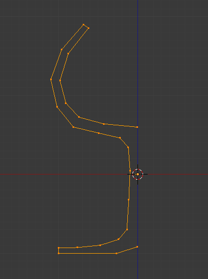
Glass profile.
First, create a mesh representing the profile of your object. If you are modeling a hollow object, it is a good idea to thicken the outline. Fig. shows the profile for a wine glass we will model as a demonstration.
Go to Edit Mode and select all the vertices of the Profile with A.
We will be rotating the object around the cursor in the top view, so switch to the top view with Numpad7.
Glass profile, top view in Edit Mode, just before spinning.
Place the cursor along the center of the profile by selecting one of the vertices along the center, and snapping the 3D cursor to that location with Mesh ‣ Cursor ‣ Selection. (Fig. Glass profile, top view in Edit Mode, just before spinning.) shows the wine glass profile from top view, with the cursor correctly positioned.
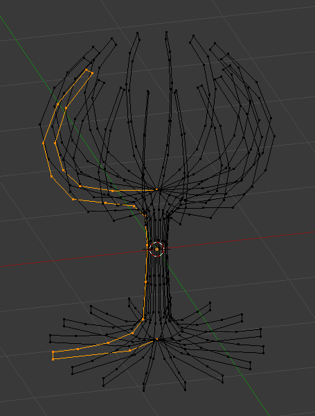
Click the Spin button. If you have more than one 3D Viewport open, the cursor will change to an arrow with a question mark and you will have to click in the area containing the top view before continuing. If you have only one 3D Viewport open, the spin will happen immediately. Fig. shows the result of a successful spin.
Duplicate
Result of spin operation. |
Duplicate vertices.
The spin operation leaves duplicate vertices along the profile. You can select all vertices at the seam with Box select B (shown in Fig. Duplicate vertices.) and perform a Merge by Distance operation.
Notice the selected vertex count before and after the Merge by Distance operation . If all goes well, the final vertex count (38 in this example) should match the number of the original profile noted in Mesh data ‣ Vertex and face numbers. If not, some vertices were missed and you will need to weld them manually. Or, worse, too many vertices will have been merged.
Note
Merging Two Vertices into One
To merge (weld) two vertices together, select both of them by Shift-RMB clicking on them. Press S to start scaling and hold down Ctrl while scaling to scale the points down to 0 units in the X, Y and Z axis. LMB to complete the scaling operation and click the Merge by Distance button in the Toolbar in Edit Mode (also available with Context Menu ‣ Merge by Distance).
Recalculate Normals
All that remains now is to recalculate the normals to the outside by selecting all vertices, pressing Ctrl-N and validating Recalculate Normals Outside in the pop-up menu.
