
实体化修改器
厚度
待实体化的深度。
Important
The modifier thickness is calculated using local vertex coordinates. If the object has a non-uniform scale, the thickness will vary on different sides of the object.
To fix this, either or Clear the scale.
钳制
A value between (0 to 2) to clamp offsets to avoid self-intersection. The amount is determined by the length of the shortest adjacent edge.
钳制偏移量。
Angle Clamp
If enabled clamping will also consider angles in the geometry, not only lengths.
顶点组
仅该组的顶点进行实体化.权重系数会乘上厚度,所以低权重的顶点会更薄。
反转
反转顶点组,让 不 属于顶点组的顶点实体化。
系数
有多少顶点权重会被考虑在内。
On 0.0 , vertices with zero weight will have no thickness at all (creates duplicate vertices).
取 0.5 时,权重为 0 的顶点的厚度是那些有最大权重顶点厚度的一半。
取 1.0 时,权重被忽略,每个顶点都会使用 厚度 值。
Bevel Convex
Edge to be added to outside edges.
偏移量
A value between (-1 to 1) to locate the solidified output inside or outside the original mesh. The inside and outside is determined by the face normals. Set to 0.0, the solidified output will be centered on the original mesh.
翻转法线
翻转所有几何形体的法线(包括内部和外部表面)。
填充边缘
填充内部和外部边之间的间隙。
In Simple Mode: Will not extrude surfaces parallel to the original one, but instead will only add the perpendicular rim.
In Complex Mode: Will only leave the generated perpendicular rim.
Note
填充边沿 和 仅边沿 仅在 非流形 物体上有区别,因为 边沿 是从原几何形体的边界产生的。
材质编号偏移
对新的几何体选择不同的材质使用。这作为实体化面的原始材质的偏移量而使用。
值为 1 则使用原始材料正下方的材质。
值为 -2 则使用原始材料上方两个单位的材质。
这些是夹在最顶部和底部材料槽。
框
同样的,你也可以赋予边沿面另一个材质。
Shell Vertex Group
Vertex group that the generated shell geometry will be weighted to. This allows you to use other modifiers to only affect the shell geometry by using a that modifier’s vertex group influence control.
Rim Vertex Group
Same as Shell Vertex Group, but for the generated rim geometry.
This is the default solidify algorithm, which simply extrudes the geometry. This algorithm does not work on geometry where edges have more than two adjacent faces.
折痕
这些选项是为了给 使用的。
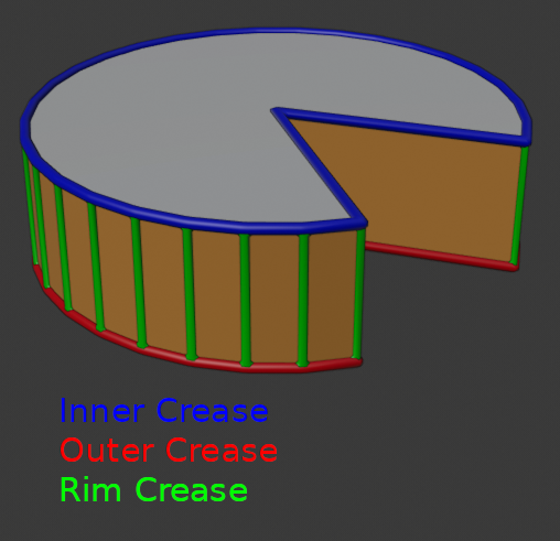
Edges which will get creases marked.
内部
为内部边设置折痕。
外表面
为外部边设置折痕。
框
为边沿边设置折痕。
均衡厚度
过调整尖角来保持厚度。有时提高质量,但也增加了计算时间。
高品质法线
Important
If the normals of adjacent faces don’t point into the same general direction, simple mode will not be able to solidify the boundary between those. This happens if the normals are not recalculated or for example on one-sided surfaces like a Möbius strip.
This is a new solidify algorithm which can handle every geometric situation to guarantee a manifold output geometry. This algorithm is able to solidify shapes like Möbius strips, Klein bottles, architectural wall layouts and many more which the standard implementation isn’t able to do. If the special cases are not present it is recommended to choose Simple Mode because the extra logic makes this algorithm much slower.
Note
There are no options for crease in the Modifier tab because crease is handled in a dynamic way. The modifier will transfer the creases of the original mesh in a smart way to the output mesh to work with the modifier.
Thickness Mode
Choose the kind of thickness handling (thickness solver)
Different thickness options on a non-manifold mesh.
Fixed
This is similar to Simple Mode without Even Thickness. The new vertices are always in a fixed distance to the old ones.
Even
This is similar to Simple Mode with Even Thickness and High Quality Normals. It adjusts for sharp corners, but may not always work when more than three faces come together.
Constraints
This is a more advanced model to try to always get the perfect thickness everywhere. For up to three faces it is always guaranteed to find a perfect solution.
Boundary Shape
Choose the kind of boundary that suits the model the most.
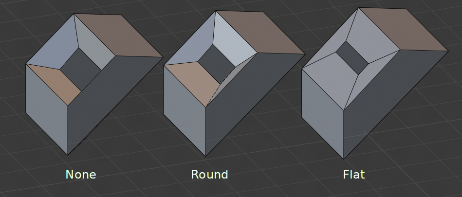
Different boundary options with a matCap.
Flat Faces
Make faces use the minimal vertex weight assigned to their vertices to ensure that new faces remain parallel to their original ones. This is slow, so disable it when it is not needed.
Merge Threshold
Distance within which degenerated geometry is merged.
已知局限
Solidify thickness is an approximation. While Even Thickness and High Quality Normals should yield good results, the final wall thickness is not guaranteed and may vary depending on the mesh topology. Especially for vertices with more than three adjacent faces.

