
Using tilemaps
Project setup
This demo we’ll use the following tiles taken from Kenney’s “Abstract Platformer” art pack. You can find the complete set but for this demo we’ll stick to this small set.
Create a new project and place the above image in the project folder.
When using a tileset, it’s important that adjacent tiles match up. Godot’s default is to import 2D images using an interpolated “filter” mode, which will result in ugly borders between the tiles. Select the image and click the Import tab. Turn off and click “Reimport”. See Importing images for details.
Add a new node to the scene. By default, a TileMap uses a square grid of tiles. You can also use a perspective-based “Isometric” mode or define your own custom tile shape.
Under the “Cell” section in the Inspector are many properties you can adjust to customize your tilemap’s behavior:
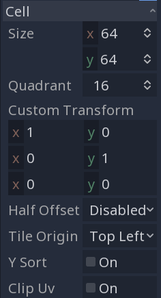
Cell SizeThis defines the size of the grid. This should match the pixel size of your tiles. The default value is
(64, 64).YSortThis causes tiles to be drawn in order of their position, so that “lower” tiles are drawn on top of “higher” ones.
Half OffsetandTile OriginThese properties affect the position of the tile relative to the grid position.
QuadrantDefines the chunk size used for batched drawing. This can negatively affect performance. Don’t change it unless you know what you’re doing.
-
Used to alter the tile’s shape. Use this if you have non-square tiles.
All of these options can be left at their defaults for this demo.
Creating a TileSet
Once you’ve configured your tilemap, it’s time to add a TileSet. A TileSet is a that contains the data about your tiles - their textures, collision shapes, and other properties. When the game runs, the TileMap combines the individual tiles into a single object.
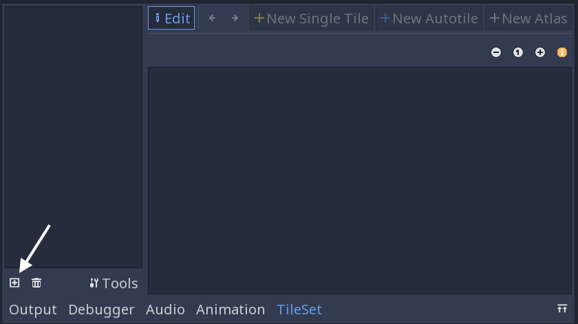
To add a new TileSet, click on the “Tile Set” property and select “New TileSet”.
Click on the TileSet property, and the “TileSet” panel will open at the bottom of the editor window:
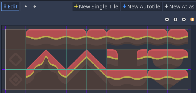
First, you need to add the texture(s) that you’ll use for the tiles. Click the “Add Texture(s) to TileSet” button and select the tilesheet.png image.
Next, click “New Single Tile” and drag in the image to select the tile you want. Click the “Enable Snap” button to make it easier to select the entire tile. A yellow rectangle appears around the selected tile.
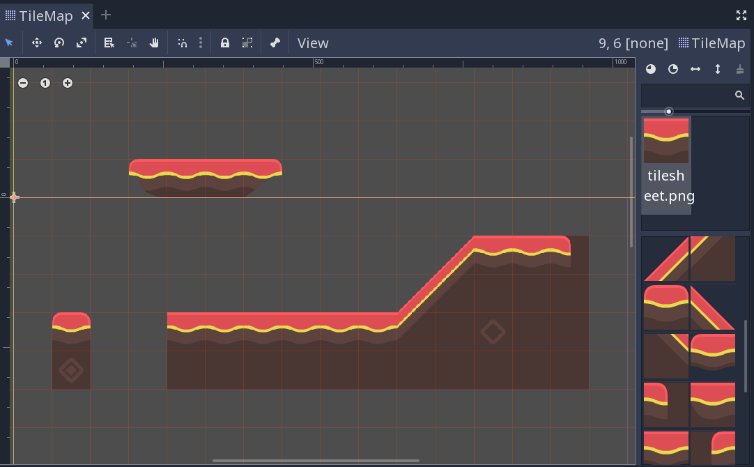
Click on the TileMap in the scene tree, and you’ll see that the newly created tile now appears on the right side. Click in the viewport and you can place tiles. Right-click to remove them.
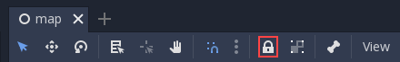
It’s easy to accidentally select and move the tilemap node. To avoid this, use the node’s lock button:
If you’re making a map that needs collisions - walls, floor, or other obstacles, for example - then you’ll need to add collision shapes to any tiles that you want to be considered “solid”.
Click “TileSet” at the bottom of the editor window to return to the tileset tool. Click the tile you previously defined (outlined in yellow). Select the “Collision” tab and click the “Create a new rectangle” button. Make sure you still have grid snap enabled, then click and drag in the tile. A square collision shape appears in light blue:
You can add occlusion and navigation shapes to the tile in the same way.
Atlas tiles
Rather than adding individual tiles one at a time, you can define a group of tiles all at once using an atlas. This also allows you to randomly generate tiles from the group.
Click “New Atlas” and drag to select the entire tile sheet.
If you haven’t already, make sure to change the “Step” in the snap settings to (64, 64), or your tiles may be chopped into smaller pieces. You can find this in the Inspector:
Once you’ve defined the atlas you can add collision shapes to the individual tiles as before. You can also click “Icon” to select one of the tiles to represent the atlas.
Back in the TileMap, you can select the atlas tile and you’ll see all of the tiles it contains:
In addition to saving time when defining the tiles, this can help by grouping similar tiles together when you’re working with a large number of tiles.
When drawing with atlas tiles, enabling the “Use priority” option causes tiles to be selected at random. By default, each tile in the tileset has an equal likelihood of occurring. You can change the likelihood by setting different priorities for each tile. For example, a tile with priority 2 is twice as likely to be selected as a tile with priority 1, and a tile with priority 3 is 50% more likely to be selected than a tile with priority 2.
Autotiles allow you to define a group of tiles, then add rules to control which tile gets used for drawing based on the content of adjacent cells.
Click “New Autotile” and drag to select the tiles you wish to use. You can add collisions, occlusion, navigation shapes, tile priorties, and select an icon tile in the same manner as for atlas tiles.
Tile selection is controlled by bitmasks. Bitmasks can be added by clicking “Bitmask”, then clicking parts of the tiles to add or remove bits in the mask. Left-clicking an area of the tile adds a bit, right-click removes “off”, and shift-left-click sets an “ignore” bit.
Whenever Godot updates a cell using an autotile, it first creates a pattern based on which adjacent cells are already set. Then, it searches the autotile for a single tile with a bitmask matching the created pattern. If no matching bitmask is found, the “icon” tile will be used instead. If more than one matching bitmask is found, one of them will be selected randomly, using the tile priorities.
The rules for matching a bitmask to a pattern depend on the tileset’s autotile bitmask mode. This can be set in the “Inspector” tab, under the “Selected Tile” heading. Allowed values are “2x2”, “3x3 (minimal)”, and “3x3”.
All “on” and “off” bits must be satisfied for a bitmask to match, but “ignore” bits are ignored.
2x2
In 2x2 mode, each bitmask contains four bits, one for each corner.
Where a bit is “on”, all cells connected to that corner must be filled using the same autotile, in order for the bitmask to match. For example, if the top-left bit is set, the cell directly above, directly left, and diagonally above-left must be filled.
Where a bit is “off”, at least one cell connected to that corner must not be set using the same autotile.
At least one bit must be set for the tile to be used, so a total of 15 tiles would be needed to provide exactly one tile for each arrangement that this mode can test for.
2x2 mode can only match cells that are part of a 2-by-2 block - cells with no neighbors and lines only one cell wide are not supported.
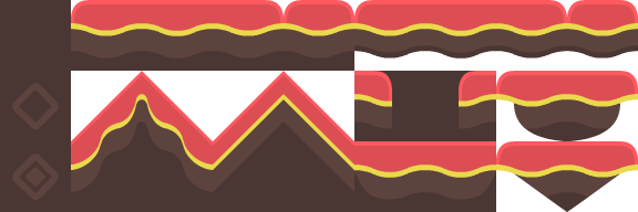
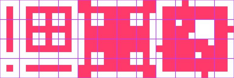
Template - Generic:
This template can be used for sideways or fully top-down perspectives. It’s designed for a TileMap cell size of 64x64.
- White: “off”
In 3x3 (minimal) mode, each bitmask contains 9 bits (4 corners, 4 edges, 1 center). The 4 corner bits work the same as in 2x2 mode.
When an edge bit is “on”, the cell which shares that edge must be filled. When an edge bit is “off”, the cell which shares that edge must be empty.
The center bit should be “on” for any tile you wish to use. Note that in this mode, it makes no sense for a corner bit to be “on” when either edge bit adjacent to it is not “on”.
A total of 47 tiles would be needed to provide exactly one bitmask for each arrangement that this mode can test for.
Note
Right-click an image and choose Save image as… to save it.
Template - Generic:
This template can be used for sideways or fully top-down perspectives. All templates below are designed for a TileMap cell size of 64x64, but you may have to use different subtile sizes for top-down templates as described below.
Key:
- Red: “on”
- White: “off”
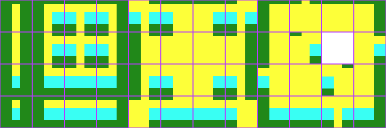
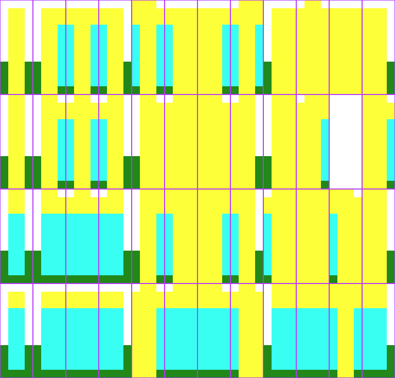
Template - Top-down floor in 3/4 perspective:
Key (applies to the four templates below):
- Green: floor
- Cyan: wall
- Yellow: top of wall
- Transparent: air
Template - Top-down wall in 3/4 perspective:
Template - Top-down wall in 3/4 perspective (thick walls):
When using this template, set the TileSet subtile size to Vector2(64, 88).
Template - Top-down wall in 3/4 perspective (tall walls):
When using this template, set the “Snap Options” Step to Vector2(64, 184) and the “Selected Tile” Texture offset to height minus the cell size. This means the texture offset should be :
3x3
In 3x3 mode, each bitmaks contains 9 bits (4 corners, 4 edges, 1 center)
Each bit checks a single adjacent cell. Corner bits only check diagonally adjacent cells. The center bit should be “on” for any tile you wish to use.
A total of 256 tiles would be needed to provide exactly one bitmask for each arrangement that this mode can test for.
When using an autotile, it is possible to turn of the autotile behaviour and select tiles manually, by clicking “Disable Autotile” at the top of the tile selection window.
Autotile binding
By default, autotile only checks for adjacent cells filled using the same autotile. This behaviour can be overridden in order to have autotiles bind to each other, or even bind to empty cells. At present, this can only be done through scripting. You will need to add a script to your tileset, and define a function named “_is_tile_bound(drawn_id, neighbor_id)”. This function will be called for each adjacent cell that does not contain the same autotile, and should return true if you want the drawn cell to “bind” to the neighbor cell. You can find the id of an autotile using “find_tile_by_name(name)”, empty cells are given an id of -1.
Note that to use this in the editor, the script should start with a “tool” declaration, and you may need to close and reload the scene for these changes to take effect.
Tips and tricks
- If you’re using a Camera2D to scroll your level, you may notice lines appearing between your tiles. To fix this, open Project Settings and enable “Use Pixel Snap” in the “Rendering/Quality” section.
- You can flip and rotate tiles using the icons at the top right of the editor.
- Tools such as copy, paste, and bucket fill, can be found in the “TileMap” menu in the upper-right.

