
Introduction to 3D
In 3D, math is a little more complex than in 2D, so also checking the entry in the wiki (which was especially created for game developers, not mathematicians or engineers) will help pave the way for you to develop 3D games efficiently.
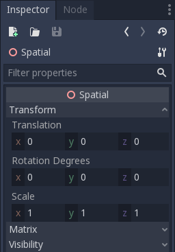
Node2D is the base node for 2D. is the base node for everything GUI. Following this reasoning, the 3D engine uses the Spatial node for everything 3D.
Spatial nodes have a local transform, which is relative to the parent node (as long as the parent node is also of or inherits from the type Spatial). This transform can be accessed as a 4×3 , or as 3 Vector3 members representing location, Euler rotation (X, Y and Z angles) and scale.
Unlike 2D, where loading image content and drawing is straightforward, 3D is a little more difficult. The content needs to be created with special 3D tools (usually referred to as DCCs) and exported to an exchange file format in order to be imported in Godot (3D formats are not as standardized as images).
There are two pipelines to import 3D models in Godot. The first and most common one is by , which allows you to import entire scenes (just as they look in the DCC), including animation, skeletal rigs, blend shapes, etc.
The second pipeline is by importing simple .OBJ files as mesh resources, which can be then put inside a MeshInstance node for display.
Generated geometry
It is possible to create custom geometry by using the resource directly. Simply create your arrays and use the ArrayMesh.add_surface_from_arrays() function. A helper class is also available, , which provides a more straightforward API and helpers for indexing, generating normals, tangents, etc.
In any case, this method is meant for generating static geometry (models that will not be updated often), as creating vertex arrays and submitting them to the 3D API has a significant performance cost.
Immediate geometry
If, instead, there is a requirement to generate simple geometry that will be updated often, Godot provides a special node, ImmediateGeometry, which provides an OpenGL 1.x style immediate-mode API to create points, lines, triangles, etc.
While Godot packs a powerful 2D engine, many types of games use 2D in a 3D environment. By using a fixed camera (either orthogonal or perspective) that does not rotate, nodes such as and AnimatedSprite3D can be used to create 2D games that take advantage of mixing with 3D backgrounds, more realistic parallax, lighting/shadow effects, etc.
Besides editing a scene, it is often common to edit the environment. Godot provides a node that allows changing the background color, mode (as in, put a skybox), and applying several types of built-in post-processing effects. Environments can also be overridden in the Camera.
Editing 3D scenes is done in the 3D tab. This tab can be selected manually, but it will be automatically enabled when a Spatial node is selected.
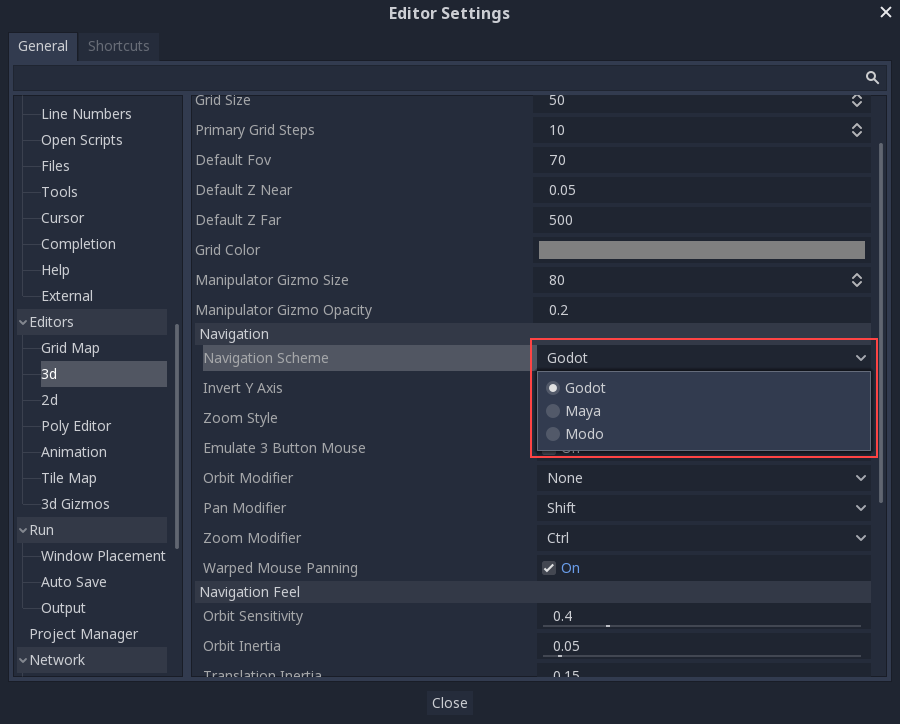
Default 3D scene navigation controls are similar to Blender (aiming to have some sort of consistency in the free software pipeline..), but options are included to customize mouse buttons and behavior to be similar to other tools in the Editor Settings:
Coordinate system
Godot uses the metric system for everything. 3D Physics and other areas are tuned for this, so attempting to use a different scale is usually a bad idea (unless you know what you are doing).
When working with 3D assets, it’s always best to work in the correct scale (set your DCC to metric). Godot allows scaling post-import and, while this works in most cases, in rare situations it may introduce floating-point precision issues (and thus, glitches or artifacts) in delicate areas, such as rendering or physics, so make sure your artists always work in the right scale!
The Y coordinate is used for “up”, though for most objects that need alignment (like lights, cameras, capsule collider, vehicle, etc.), the Z axis is used as a “pointing towards” direction. This convention roughly means that:
- X is sides
- Y is up/down
- Z is front/back
Space and manipulation gizmos
Moving objects in the 3D view is done through the manipulator gizmos. Each axis is represented by a color: Red, Green, Blue represent X, Y, Z respectively. This convention applies to the grid and other gizmos too (and also to the shader language, ordering of components for Vector3, Color, etc.).
Some useful keybindings:
- To snap placement or rotation, press Ctrl while moving, scaling or rotating.
- To center the view on the selected object, press F.
The view options are controlled by the “View” menu in the viewport’s toolbar.
You can hide the gizmos in the 3D view of the editor through this menu:
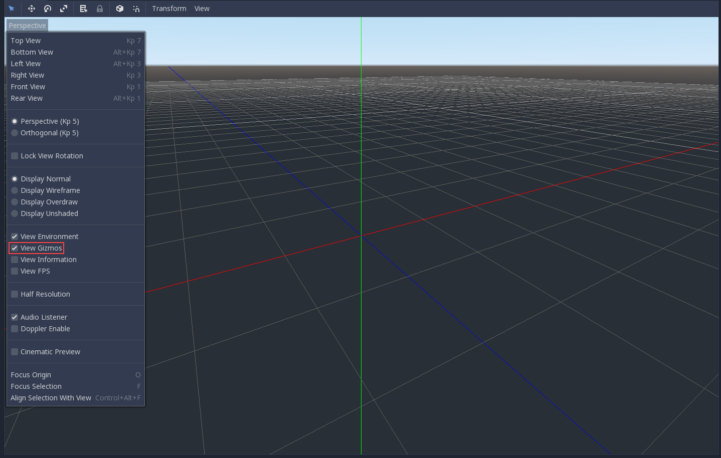
To hide a specific type of gizmos, you can toggle them off in the “View” menu.
Default environment
When created from the Project Manager, the 3D environment has a default sky.
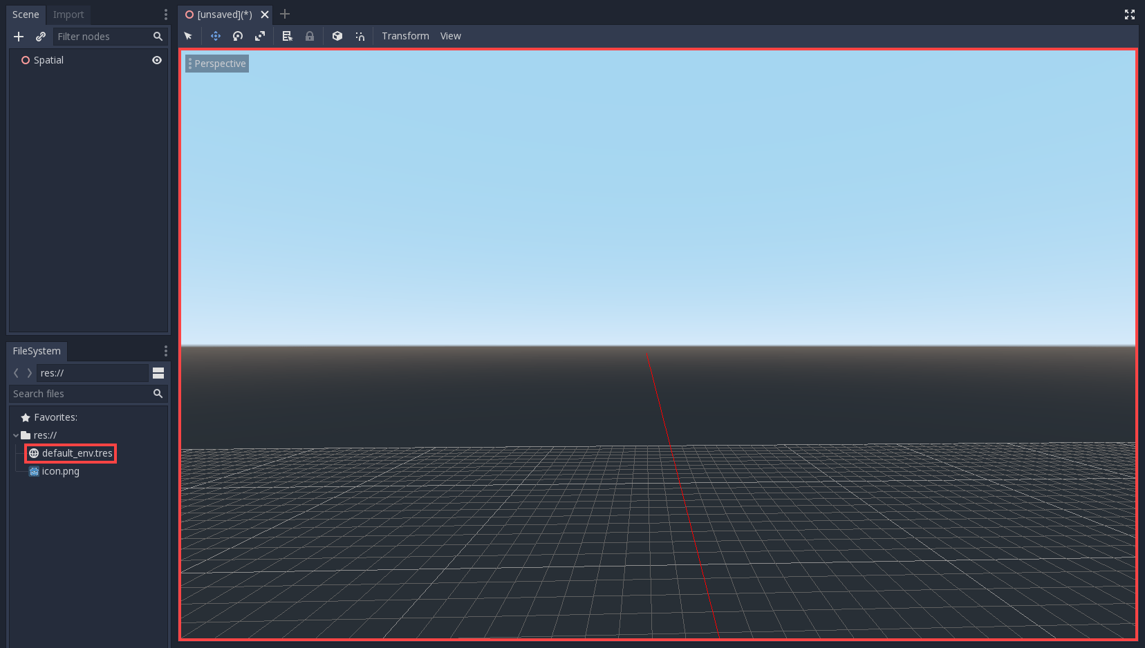
Given how physically based rendering works, it is advised to always try to work with a default environment in order to provide indirect and reflected light to your objects.
Cameras
No matter how many objects are placed in the 3D space, nothing will be displayed unless a is also added to the scene. Cameras can work in either orthogonal or perspective projections:
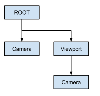
Cameras are associated with (and only display to) a parent or grandparent viewport. Since the root of the scene tree is a viewport, cameras will display on it by default, but if sub-viewports (either as render target or picture-in-picture) are desired, they need their own children cameras to display.
When dealing with multiple cameras, the following rules are enforced for each viewport:
- If no cameras are present in the scene tree, the first one that enters it will become the active camera. Further cameras entering the scene will be ignored (unless they are set as current).
- If an active camera leaves the scene tree, the first camera in tree-order will take its place.

